Friday, August 20, 2004
On-The-Go Supplement - Point-to-Point Connectivity for USB.
On-The-Go Supplement - Point-to-Point Connectivity for USB
While USB has many advantages in the plug’n’play and ease of use arena, it could never be a direct replacement for many RS-232 systems until now. One of the biggest problems with USB is that its host controlled. Unlike its firewire equivalent, if you switch off a USB host, nothing else works. USB does not support peer to peer comunication. One device on the bus must be a host.
This is fine in the general computing environment, but will cause problems in industrial applications and mobile computing enviroments. For example, a RS-232 modem was a DCE device. Simply inserting a null modem would allow it to talk to other DCE devices, so you could connect a modem up to your datalogger, PLC, printer or other RS-232 device. These devices could either talk together or to a computer. However with todays USB modems you can connect it up to your computer(host) and well, that’s about it.
Many USB digital cameras can download data to a PC, but you are unable to connect them directly to your USB printer to print the pictures out or to a CD Burner to permamently store your holiday snaps, something which is possible with other communication mediums. PDA’s can download and upload data from the PC over it's USB link, but the user can’t connect a printer, mobile phone (modem) or camera to it. This turns out to be quite a restriction to USB’s so called ease of use and simplicity . . .
So to combat these problems, a tack on standard was created to USB 2.0. This is called the On-The-Go Supplement or OTG for short. The OTG specification details the "dual role device". This is a device which can function as both a device controller (DC) and/or a host controller (HC). Aimed at embedded applications the specification doesn’t require a fully blown, resource hungry host capability.
The OTG host can have a targeted peripheral list. This means the embedded device does not need to have a list of every product and vendor ID or class driver. It can target only one type of periheral if needed. This could for example be a modem complying to the Communication Device Class Specification.
The spec also details a Session Request Protocol (SRP) which allows a B-device (Peripheral) to nudge an A-device to turn on the USB's Vbus so it can communicate with each other. A Host Negotiation Protocol (HNP) is also added to allow either end to swap between a host or slave. As power may be a problem with battery operated hosts, the spec allows for a relaxed power source. A dual-role device needs only source a minimum of 8 mA on Vbus.
As a device can be either a host (A-device) or peripheral (B-device) and that the USB specification calls for different types of connectors for upstream and downstream ports, the OTG spec introduced two additional connectors. One such connector is a mini A/B connector allowing a mini A or mini B connector to plug into the one recepticle. A dual-role device is required to be able to detect whether a Mini-A or Mini-B plug is inserted by determining if the ID pin (an extra pin introduced by OTG) is connected to ground.
And where would OTG be without it’s own descriptor? Any dual role host can request an OTG descriptor from a B-device describing wheather or not it can handle SRP and/or HNP. Any B-device that supports either HNP or SRP must respond to this request.
The On-The-Go specification is in its last stages of revision. Revision 0.9 released on September the 5th, 2001 is currently avalible at http://www.usb.org/developers/onthego/
ISP1161 Full-speed Universal Serial Bus single-chip host and device controller.
Philips have released the ISP1161 - the world's first single-chip, integrated host and device controller conforming to the USB Revision 1.1. It has been used by Philips to demonstrate USB OTG functionallity, but also makes an excellent host controller for embedded systems such as Linux.
->Combines a USB Host Controller and USB Device Controller in a single chip.
->Can function as a USB Host only, USB Device Only or both simultaneously.
->Selectable one or two downstream ports for HC and one upstream port for DC.
->Supports single-cycle burst mode and multiple-cycle burst mode DMA operations.
->Built in separate FIFO buffer RAM for HC (4 kbytes) and DC (2462 bytes).
->6 MHz crystal oscillator with integrated PLL for low EMI.
->USB device functionally simular to the ISP1181.
->USB Host Controller registers compatible to OpenHCI although accessed though two memory map locations.
->Available in a LQFP64 package.
The ISP1161 has a standard CS, RD, WR, and D[15..0] bus making interfacing to most microcontrollers a piece of cake. This particular device only has two address lines hogging up a minimal 4 locations/ports in memory. The 4 addresses are the HC data port, HC command port, DC data port and DC command port making it one of these devices where you send a command first, then data to a different port. However to speed things along shared DMA functionality is added.
While the Host device is controlled using two memory locations, the register set is made compatible to the OpenHCI register set further aiding portability. This allowed the linux OHCI drivers to be ported reasonably easily.
While Philips introduced this device with their OTG promotional release, this device is not 100% OTG complaint. You have to remember that Philips first released this device in July 2001, the OTG specification revision 0.9 was released in early September 2001 and is still not fully qualified at time of writing.
As introduced earlier, the OTG Session Request Protocol (SRP) allows devices to turn on Vbus enabling USB connectivity. This must be done by the B-device using both the "data-line pulsing" and "VBUS pulsing" methods. The OTG host needs only support one of these. In data-line pulsing the B-device can turn on its D+ pull up resistor for a period of 5 to 10mS.
Vbus pulsing is slightly more complicated. If a OTG Complaint B-device is connected to a standard host such as the one in your computer, pulsing Vbus when your computer is powered off could lead to damage. This is overcome by the value of decoupling capacitor on the Vbus line. The USB 2.0 spec calls for a minimum of 120uF on the host's Vbus.
The OTG states that a dual role device should have between 1.0 µF and 6.5 µF. Therefore the B device can send a pulse of duration long enough that a 6.5uF capacitor on the dual role device will charge up beyond 2.1V, yet if connected to a normal host with a capacitance on Vbus of 120uF or more it will not be charged over 2.0V preventing possible damage to the host. It’s own capacitance on Vbus needs to be facted into this calulation and stricter limits are imposed by the OTG standard.
The ISP1161 does not have hardware functionailty to support SRP or HNP. Philips however informs us that they will soon offer an OTG host/device controller based on their proven ISP1161 and an OTG version of their transceiver with OTG SRP & HNP support. This will probaby come about once the OTG standard is finalised.
Device Descriptors
The device descriptor of a USB device represents the entire device. As a result a USB device can only have one device descriptor. It specifies some basic, yet important information about the device such as the supported USB version, maximum packet size, vendor and product IDs and the number of possible configurations the device can have. The format of the device descriptor is shown below.
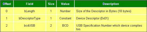
->The bcdUSB field reports the highest version of USB the device supports. The value is in binary coded decimal with a format of 0xJJMN where JJ is the major version number, M is the minor version number and N is the sub minor version number. e.g. USB 2.0 is reported as 0x0200, USB 1.1 as 0x0110 and USB 1.0 as 0x0100.
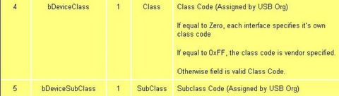
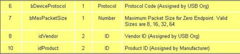
->The bDeviceClass, bDeviceSubClass and bDeviceProtocol are used by the operating system to find a class driver for your device. Typically only the bDeviceClass is set at the device level. Most class specifications choose to identify itself at the interface level and as a result set the bDeviceClass as 0x00. This allows for the one device to support multiple classes.
->The bMaxPacketSize field reports the maximum packet size for endpoint zero. All devices must support endpoint zero.
->The idVendor and idProduct are used by the operating system to find a driver for your device. The Vendor ID is assigned by the USB-IF.
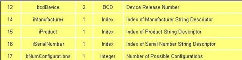
->The bcdDevice has the same format than the bcdUSB and is used to provide a device version number. This value is assigned by the developer.
->Three string descriptors exist to provide details of the manufacturer, product and serial number. There is no requirement to have string descriptors. If no string descriptor is present, a index of zero should be used.
->bNumConfigurations defines the number of configurations the device supports at its current speed.
->The bcdUSB field reports the highest version of USB the device supports. The value is in binary coded decimal with a format of 0xJJMN where JJ is the major version number, M is the minor version number and N is the sub minor version number. e.g. USB 2.0 is reported as 0x0200, USB 1.1 as 0x0110 and USB 1.0 as 0x0100.
->The bDeviceClass, bDeviceSubClass and bDeviceProtocol are used by the operating system to find a class driver for your device. Typically only the bDeviceClass is set at the device level. Most class specifications choose to identify itself at the interface level and as a result set the bDeviceClass as 0x00. This allows for the one device to support multiple classes.
->The bMaxPacketSize field reports the maximum packet size for endpoint zero. All devices must support endpoint zero.
->The idVendor and idProduct are used by the operating system to find a driver for your device. The Vendor ID is assigned by the USB-IF.
->The bcdDevice has the same format than the bcdUSB and is used to provide a device version number. This value is assigned by the developer.
->Three string descriptors exist to provide details of the manufacturer, product and serial number. There is no requirement to have string descriptors. If no string descriptor is present, a index of zero should be used.
->bNumConfigurations defines the number of configurations the device supports at its current speed.
Thursday, August 19, 2004
Control Transfers
Control transfers are typically used for command and status operations. They are essential to set up a USB device with all enumeration functions being performed using control transfers. They are typically bursty, random packets which are initiated by the host and use best effort delivery. The packet length of control transfers in low speed devices must be 8 bytes, high speed devices allow a packet size of 8, 16, 32 or 64 bytes and full speed devices must have a packet size of 64 bytes.
A control transfer can have up to three stages.
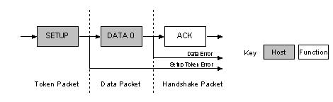
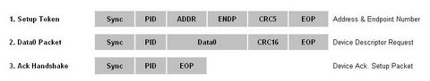
->The Setup Stage is where the request is sent. This consists of three packets. The setup token is sent first which contains the address and endpoint number. The data packet is sent next and always has a PID type of data0 and includes a setup packet which details the type of request. We detail the setup packet later. The last packet is a handshake used for acknowledging successful receipt or to indicate an error. If the function successfully receives the setup data (CRC and PID etc OK) it responds with ACK, otherwise it ignores the data and doesn’t send a handshake packet. Functions cannot issue a STALL or NAK packet in response to a setup packet.
->The optional Data Stage consists of one or multiple IN or OUT transfers. The setup request indicates the amount of data to be transmitted in this stage. If it exceeds the maximum packet size, data will be sent in multiple transfers each being the maximum packet length except for the last packet.
The data stage has two different scenarios depending upon the direction of data transfer.
------>IN: When the host is ready to receive control data it issues an IN Token.If the
function receives the IN token with an error e.g. the PID doesn't match the inverted
PID bits, then it ignores the packet. If the token was received correctly, the device can
either reply with a DATA packet containing the control data to be sent, a stall packet
indicating the endpoint has had a error or a NAK packet indicating to the host that the
endpoint is working, but temporary has no data to send
----->OUT: When the host needs to send the device a control data packet, it issues an OUT token followed by a data packet containing the control data as the payload. If any part of the OUT token or data packet is corrupt then the function ignores the packet. If the function's endpoint buffer was empty and it has clocked the data into the endpoint buffer it issues an ACK informing the host it has successfully received the data. If the endpoint buffer is not empty due to processing of the previous packet, then the function returns a NAK. However if the endpoint has had a error and its halt bit has been set, it returns a STALL.
->Status Stage reports the status of the overall request and this once again varies due to direction of transfer. Status reporting is always performed by the function.
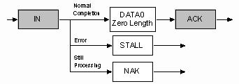
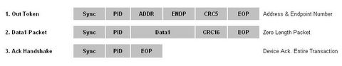
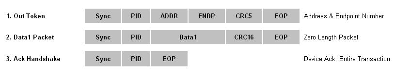
----->IN: If the host sent IN token(s) during the data stage to receive data, then the host must acknowledge the successful recept of this data. This is done by the host sending an OUT token followed by a zero length data packet. The function can now report its status in the handshaking stage. An ACK indicates the function has completed the command is now ready to accept another command. If an error occurred during the processing of this command, then the function will issue a STALL. However if the function is still processing, it returns a NAK indicating to the host to repeat the status stage later.
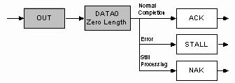
----->OUT: If the host sent OUT token(s) during the data stage to transmit data, the function will acknowledge the successful recept of data by sending a zero length packet in response to an IN token. However if an error occurred, it should issue a STALL or if it is still busy processing data, it should issue a NAK asking the host to retry the status phase later
Control Transfers : The bigger picture
Now how does all this fit together? Let's say for example, the Host wants to request a device descriptor during enumeration. The packets which are sent are as follows.
The host will send the Setup token telling the function that the following packet is a Setup packet. The Address field will hold the address of the device the host is requesting the descriptor from. The endpoint number should be zero, specifying the default pipe. The host will then send a DATA0 packet. This will have an 8 byte payload which is the Device Descriptor Request as outlined in Chapter 9 of the USB Specification. The USB function then acknowledges the setup packet has been read correctly with no errors. If the packet was received corrupt, the device just ignores this packet. The host will then resend the packet after a short delay.
The above three packets represent the first USB transaction. The USB device will now decode the 8 bytes received, and determine it was a device descriptor request. The device will then attempt to send the Device Descriptor, which will be the next USB transaction.
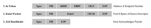
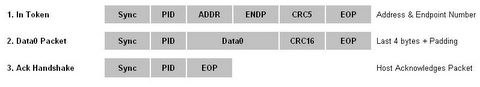
In this case, we assume that the maximum payload size is 8 bytes. The host sends the IN token, telling the device it can now send data for this endpoint. As the maximum packet size is 8 bytes, we must split up the 12 byte device descriptor into chunks to send. Each chunk must be 8 bytes except for the last transaction. The host acknowledges every data packet we send it.
Once the device descriptor is sent, a status transaction follows. If the transactions were successful, the host will send a zero length packet indicating the overall transaction was successful. The function then replies to this zero length packet indicating its status.
A control transfer can have up to three stages.
->The Setup Stage is where the request is sent. This consists of three packets. The setup token is sent first which contains the address and endpoint number. The data packet is sent next and always has a PID type of data0 and includes a setup packet which details the type of request. We detail the setup packet later. The last packet is a handshake used for acknowledging successful receipt or to indicate an error. If the function successfully receives the setup data (CRC and PID etc OK) it responds with ACK, otherwise it ignores the data and doesn’t send a handshake packet. Functions cannot issue a STALL or NAK packet in response to a setup packet.

->The optional Data Stage consists of one or multiple IN or OUT transfers. The setup request indicates the amount of data to be transmitted in this stage. If it exceeds the maximum packet size, data will be sent in multiple transfers each being the maximum packet length except for the last packet.
The data stage has two different scenarios depending upon the direction of data transfer.
------>IN: When the host is ready to receive control data it issues an IN Token.If the
function receives the IN token with an error e.g. the PID doesn't match the inverted
PID bits, then it ignores the packet. If the token was received correctly, the device can
either reply with a DATA packet containing the control data to be sent, a stall packet
indicating the endpoint has had a error or a NAK packet indicating to the host that the
endpoint is working, but temporary has no data to send

----->OUT: When the host needs to send the device a control data packet, it issues an OUT token followed by a data packet containing the control data as the payload. If any part of the OUT token or data packet is corrupt then the function ignores the packet. If the function's endpoint buffer was empty and it has clocked the data into the endpoint buffer it issues an ACK informing the host it has successfully received the data. If the endpoint buffer is not empty due to processing of the previous packet, then the function returns a NAK. However if the endpoint has had a error and its halt bit has been set, it returns a STALL.
->Status Stage reports the status of the overall request and this once again varies due to direction of transfer. Status reporting is always performed by the function.
----->IN: If the host sent IN token(s) during the data stage to receive data, then the host must acknowledge the successful recept of this data. This is done by the host sending an OUT token followed by a zero length data packet. The function can now report its status in the handshaking stage. An ACK indicates the function has completed the command is now ready to accept another command. If an error occurred during the processing of this command, then the function will issue a STALL. However if the function is still processing, it returns a NAK indicating to the host to repeat the status stage later.

----->OUT: If the host sent OUT token(s) during the data stage to transmit data, the function will acknowledge the successful recept of data by sending a zero length packet in response to an IN token. However if an error occurred, it should issue a STALL or if it is still busy processing data, it should issue a NAK asking the host to retry the status phase later

Control Transfers : The bigger picture
Now how does all this fit together? Let's say for example, the Host wants to request a device descriptor during enumeration. The packets which are sent are as follows.
The host will send the Setup token telling the function that the following packet is a Setup packet. The Address field will hold the address of the device the host is requesting the descriptor from. The endpoint number should be zero, specifying the default pipe. The host will then send a DATA0 packet. This will have an 8 byte payload which is the Device Descriptor Request as outlined in Chapter 9 of the USB Specification. The USB function then acknowledges the setup packet has been read correctly with no errors. If the packet was received corrupt, the device just ignores this packet. The host will then resend the packet after a short delay.

The above three packets represent the first USB transaction. The USB device will now decode the 8 bytes received, and determine it was a device descriptor request. The device will then attempt to send the Device Descriptor, which will be the next USB transaction.


In this case, we assume that the maximum payload size is 8 bytes. The host sends the IN token, telling the device it can now send data for this endpoint. As the maximum packet size is 8 bytes, we must split up the 12 byte device descriptor into chunks to send. Each chunk must be 8 bytes except for the last transaction. The host acknowledges every data packet we send it.
Once the device descriptor is sent, a status transaction follows. If the transactions were successful, the host will send a zero length packet indicating the overall transaction was successful. The function then replies to this zero length packet indicating its status.
Bulk Transfers
Bulk transfers can be used for large bursty data. Such examples could include a print-job sent to a printer or an image generated from a scanner. Bulk transfers provide error correction in the form of a CRC16 field on the data payload and error detection/re-transmission mechanisms ensuring data is transmitted and received without error.
Bulk transfers will use spare un-allocated bandwidth on the bus after all other transactions have been allocated. If the bus is busy with isochronous and/or interrupt then bulk data may slowly trickle over the bus. As a result Bulk transfers should only be used for time insensitive communication as there is no guarantee of latency.
Bulk Transfers
->Used to transfer large bursty data.
->Error detection via CRC, with guarantee of delivery.
->No guarantee of bandwidth or minimum latency.
->Stream Pipe - Unidirectional
->Full & high speed modes only.
Bulk transfers are only supported by full and high speed devices. For full speed endpoints, the maximum bulk packet size is either 8, 16, 32 or 64 bytes long. For high speed endpoints, the maximum packet size can be up to 512 bytes long. If the data payload falls short of the maximum packet size, it doesn't need to be padded with zeros. A bulk transfer is considered complete when it has transferred the exact amount of data requested, transferred a packet less than the maximum endpoint size of transferred a zero-length packet.
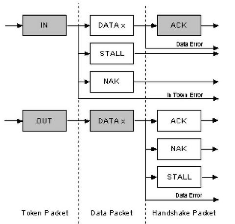
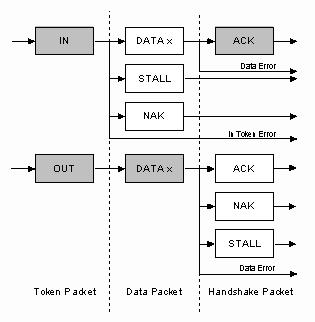
The above diagram shows the format of a bulk IN and OUT transaction.
->IN: When the host is ready to receive bulk data it issues an IN Token. If the function receives the IN token with an error, it ignores the packet. If the token was received correctly, the function can either reply with a DATA packet containing the bulk data to be sent, or a stall packet indicating the endpoint has had a error or a NAK packet indicating to the host that the endpoint is working, but temporary has no data to send.
->OUT: When the host wants to send the function a bulk data packet, it issues an OUT token followed by a data packet containing the bulk data. If any part of the OUT token or data packet is corrupt then the function ignores the packet. If the function's endpoint buffer was empty and it has clocked the data into the endpoint buffer it issues an ACK informing the host it has successfully received the data. If the endpoint buffer is not empty due to processing a previous packet, then the function returns an NAK. However if the endpoint has had an error and it's halt bit has been set, it returns a STALL
Bulk transfers will use spare un-allocated bandwidth on the bus after all other transactions have been allocated. If the bus is busy with isochronous and/or interrupt then bulk data may slowly trickle over the bus. As a result Bulk transfers should only be used for time insensitive communication as there is no guarantee of latency.
Bulk Transfers
->Used to transfer large bursty data.
->Error detection via CRC, with guarantee of delivery.
->No guarantee of bandwidth or minimum latency.
->Stream Pipe - Unidirectional
->Full & high speed modes only.
Bulk transfers are only supported by full and high speed devices. For full speed endpoints, the maximum bulk packet size is either 8, 16, 32 or 64 bytes long. For high speed endpoints, the maximum packet size can be up to 512 bytes long. If the data payload falls short of the maximum packet size, it doesn't need to be padded with zeros. A bulk transfer is considered complete when it has transferred the exact amount of data requested, transferred a packet less than the maximum endpoint size of transferred a zero-length packet.

The above diagram shows the format of a bulk IN and OUT transaction.
->IN: When the host is ready to receive bulk data it issues an IN Token. If the function receives the IN token with an error, it ignores the packet. If the token was received correctly, the function can either reply with a DATA packet containing the bulk data to be sent, or a stall packet indicating the endpoint has had a error or a NAK packet indicating to the host that the endpoint is working, but temporary has no data to send.
->OUT: When the host wants to send the function a bulk data packet, it issues an OUT token followed by a data packet containing the bulk data. If any part of the OUT token or data packet is corrupt then the function ignores the packet. If the function's endpoint buffer was empty and it has clocked the data into the endpoint buffer it issues an ACK informing the host it has successfully received the data. If the endpoint buffer is not empty due to processing a previous packet, then the function returns an NAK. However if the endpoint has had an error and it's halt bit has been set, it returns a STALL
Isochronous Transfers
Isochronous transfers occur continuously and periodically. They typically contain time sensitive information, such as an audio or video stream. If there were a delay or retry of data in an audio stream, then you would expect some erratic audio containing glitches. The beat may no longer be in sync. However if a packet or frame was dropped every now and again, it is less likely to be noticed by the listener.
Isochronous Transfers provide
->Guaranteed access to USB bandwidth.
->Bounded latency.
->Stream Pipe - Unidirectional
->Error detection via CRC, but no retry or guarantee of delivery.
->Full & high speed modes only.
->No data toggling.
The maximum size data payload is specified in the endpoint descriptor of an Isochronous Endpoint. This can be up to a maximum of 1023 bytes for a full speed device and 1024 bytes for a high speed device. As the maximum data payload size is going to effect the bandwidth requirements of the bus, it is wise to specify a conservative payload size. If you are using a large payload, it may also be to your advantage to specify a series of alternative interfaces with varying isochronous payload sizes. If during enumeration, the host cannot enable your preferred isochronous endpoint due to bandwidth restrictions, it has something to fall back on rather than just failing completely. Data being sent on an isochronous endpoint can be less than the pre-negotiated size and may vary in length from transaction to transaction.
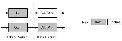
The above diagram shows the format of an Isochronous IN and OUT transaction. Isochronous transactions do not have a handshaking stage and cannot report errors or STALL/HALT conditions.
Interrupt Transfers
Any one who has had experience of interrupt requests on microcontrollers will know that interrupts are device generated. However under USB if a device requires the attention of the host, it must wait until the host polls it before it can report that it needs urgent attention!
Interrupt Transfers
->Guaranteed Latency
->Stream Pipe - Unidirectional
->Error detection and next period retry.
Interrupt transfers are typically non-periodic, small device "initiated" communication requiring bounded latency. An Interrupt request is queued by the device until the host polls the USB device asking for data.
->The maximum data payload size for low-speed devices is 8 bytes.
->Maximum data payload size for full-speed devices is 64 bytes.
->Maximum data payload size for high-speed devices is 1024 bytes
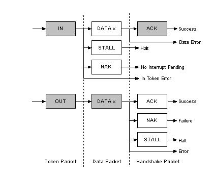
The above diagram shows the format of an Interrupt IN and Interrupt OUT transaction.
->IN: The host will periodically poll the interrupt endpoint. This rate of polling is specified in the endpoint descriptor which is covered later. Each poll will involve the host sending an IN Token. If the IN token is corrupt, the function ignores the packet and continues monitoring the bus for new tokens.
If an interrupt has been queued by the device, the function will send a data packet containing data relevant to the interrupt when it receives the IN Token. Upon successful recept at the host, the host will return an ACK. However if the data is corrupted, the host will return no status. If on the other hand a interrupt condition was not present when the host polled the interrupt endpoint with an IN token, then the function signals this state by sending a NAK. If an error has occurred on this endpoint, a STALL is sent in reply to the IN token instead.
->OUT: When the host wants to send the device interrupt data, it issues an OUT token followed by a data packet containing the interrupt data. If any part of the OUT token or data packet is corrupt then the function ignores the packet. If the function's endpoint buffer was empty and it has clocked the data into the endpoint buffer it issues an ACK informing the host it has successfully received the data. If the endpoint buffer is not empty due to processing of a previous packet, then the function returns an NAK. However if an error occurred with the endpoint consequently and its halt bit has been set, it returns a STALL.
![]()